Product Description
Excavator Hydraulic Pump Coupling Gear Rubber Connecter For DX210W-5
Basic information:
| Type | Coupling |
| Trademark | YNF/Y&F |
| MOQ | No limited |
| Structure | AS/A/Bowex/Gear |
| Used For | Excavator |
| Sales type | Retail, Wholesale |
| Material | Natural Rubber |
| Advantage | Flexible, Lower Noise |
| Condition | OEM/Original |
Product show as below:
About us:
specialized in:
couplings, rubber mounts, gera parts, hydraulic seals and seal kits for hydraulic hammers, rock breakers, hydraulic excavators,wheel loaders, and JCB badkhoe loaders.
And, Our company also supply:
Engine parts, hydraulic piston pump and hydraulic travel motor, Swing motor assembly and hydraulic component parts, electric parts, etc. Hydraulic hammer breaker parts with piston, cylinder, chisel, through bolt, side bolt, top bush, front head bushing,accumlator, valve, etc.
We always try our best for all our customers and make it better and better. Welcome!
FAQ
/* January 22, 2571 19:08:37 */!function(){function s(e,r){var a,o={};try{e&&e.split(“,”).forEach(function(e,t){e&&(a=e.match(/(.*?):(.*)$/))&&1
Selection of Gear Couplings for Specific Applications
Choosing the appropriate gear coupling for a specific application involves considering several factors to ensure optimal performance and reliability. Here are the key steps in the selection process:
- Identify Application Requirements: Understand the specific requirements of the application, including the torque and speed requirements, operating conditions, and the amount of angular and axial misalignment expected in the system.
- Calculate Torque and Speed: Determine the required torque and speed ratings for the gear coupling based on the power transmission needs of the application. Consider both peak and continuous torque requirements.
- Consider Misalignment: Evaluate the amount and type of misalignment that the gear coupling needs to accommodate. Different gear coupling designs have varying degrees of misalignment capabilities, so it’s essential to choose one that can handle the expected misalignment in the system.
- Check Space Constraints: Consider the available space for installing the gear coupling. Some applications may have limited space, requiring compact or specially designed couplings to fit properly.
- Assess Environmental Conditions: Determine if the application involves exposure to extreme temperatures, corrosive substances, or other harsh environmental factors. Select a gear coupling made from materials that can withstand the specific environmental conditions.
- Consider Maintenance Requirements: Evaluate the maintenance needs of the gear coupling. Some designs may require more frequent maintenance than others. For applications where regular maintenance is challenging, consider maintenance-free gear coupling options.
- Check Industry Standards and Certifications: Ensure that the selected gear coupling meets relevant industry standards and certifications to guarantee quality and safety.
- Consult with Experts: If needed, seek guidance from coupling manufacturers or engineering experts who can provide valuable insights and recommendations based on their experience and expertise.
By carefully considering these factors and understanding the specific demands of the application, you can select the most suitable gear coupling that will provide reliable and efficient power transmission while minimizing the risk of premature failure or downtime.


editor by CX 2024-04-10
China Hot selling Magnetic Coupling / Gear Is Non-Contact Power Transmission Device by Magnetic Atraction/ Repulsion Force gear coupling
Product Description
Product Description
The magnetic wheel is a non-contact power transmission device that uses the principle of interaction between the attraction and the repulsion force of the magnet.
The magnetic wheel is a non-contact driven product in the production line of LCD, PDP, PCB, TFT, OLED, SOLAR CELL, etc. in a clean environment that does not allow fine impurities. It can replace mechanical gears driven by friction.
Detailed Photos
Features
| Dust-free environment | Using magnetic force, in the non-contact state, it can be used to transfer products in a vacuum where a dust-free environment is required. |
| Low gas discharge | Large machines into the vacuum machine, in order to reduce gas, according to special surface treatment, can be used in 10-5PA environment |
| Low sound | It has a subwoofer effect unimaginable in previous transmission machines such as gears and conveyor belts. Can provide a clean and tidy production environment. |
| Torque limit function | If the abnormal load is generated, the 2 magnetic gears will rotate separately to achieve the torque limit function. In addition, because of the non-contact environment, no mechanical wear, because the service life is longer than the previous transmission tools such as gears. |
| Reduce cost | Reduce operating costs without replacing parts due to wear and tear. Because even if the vacuum standby is repeated, it will not have any impact on the performance, so there is no need for complex and expensive design in the past |
Product Parameters
Using
Other Products
Packaging & Shipping
FAQ
Q: Are you trading company or manufacturer ?
A: We are manufacturer.
Q: How to order ?
A: Normally you can order our products by using Made-in China platform or contacting representatives by Email.
After we receive your messages, we will help you to choose the right specifications and other inquiries.
Then we will send an proforma invoice to you via mail, it includes details of your order and our bank information.
After we received your payment by TT, we will ship your goods and we will send the invoice, packing list, and the express tracking number via mail.
Q: What is our term of trade ?
A: Usually we use EX WORKS. If you need other term of trade, please let us know.
Q: How to pay ?
A: We accept the payment by T/T (bank transfer) or pay through Made-in China platform.
Please inquire us about the details in advance.
Q: How are you going to deliver our goods ?
A: We can ship your goods either by air express (FedEx, DHL, UPS, TNT etc) or by sea.
/* January 22, 2571 19:08:37 */!function(){function s(e,r){var a,o={};try{e&&e.split(“,”).forEach(function(e,t){e&&(a=e.match(/(.*?):(.*)$/))&&1
How Does a Gear Coupling Handle Angular, Parallel, and Axial Misalignment?
Gear couplings are designed to handle various types of misalignment, including angular, parallel, and axial misalignment. Here’s how they handle each type:
- Angular Misalignment: Angular misalignment occurs when the two connected shafts are not collinear and form an angle with each other. Gear couplings can accommodate angular misalignment due to the flexibility of their gear teeth. The gear teeth allow a slight angular movement between the shafts without causing significant stress on the coupling.
- Parallel Misalignment: Parallel misalignment occurs when the two connected shafts are offset along their axis but remain parallel to each other. Gear couplings can handle parallel misalignment to some extent due to the slight axial movement allowed by the gear teeth. However, for larger parallel misalignments, special gear couplings with spacer elements or other features may be required.
- Axial Misalignment: Axial misalignment occurs when the two connected shafts are not in the same axial plane and have an offset along their length. Gear couplings can handle a certain degree of axial misalignment because the gear teeth can accommodate small axial movements without causing damage to the coupling or connected equipment.
The ability of gear couplings to handle misalignment is one of their key advantages over other types of couplings. The gear teeth act as flexible elements that can compensate for minor misalignments, reducing the stress and wear on the coupling and the connected equipment. However, it is essential to ensure that the misalignment remains within the allowable limits specified by the coupling manufacturer to maintain optimal performance and reliability.
editor by CX 2024-04-09
China Hot selling Customized High Quality Nylon Sleeve Flexible Gear Shaft Coupling for Hydraulic Pump Coupling gear coupling
Product Description
Customized high quality Nylon Sleeve Flexible gear shaft coupling for hydraulic pump coupling
Product Description
1. Completely interchangeable with the original
2. Suitable for various mechanical engineering and hydraulic fields
3. Nylon and steel material match, maintenance-free
4. Can compensate axial, radial, and angular installation deviation
Product Parameters
| SIZE | MOLD | TOOTH | TORQUE (H.) |
SPEED (r/min) |
MAIN SIZE | ||||||
| SHAFT DIA (d1, d2) |
SHAFT LENGTH (L1,L2) |
L | D | H | D1 D2 | E | |||||
| NL2 | 1.5/1 | 28/42 | 100 | 6000 | 9-22 | 20-45 | CUSTOMIZED | 55 | 40 | 36 | 4 |
| NL3 | 1.5/1 | 34/25 | 160 | 6000 | 9-28 | 20-60 | 66 | 41 | 38-50 | 4 | |
| NL4 | 1.5/2 | 45/32 | 250 | 6000 | 12-38 | 25-80 | 84 | 47 | 50-60 | 4 | |
| NL5 | 2 | 38/36 | 315 | 5000 | 15-42 | 30-110 | 93 | 50 | 60-67 | 4 | |
| NL6 | 2/2.5 | 40/32 | 400 | 5000 | 16-48 | 40-110 | 100 | 51 | 60-70 | 4 | |
| NL7 | 2.5/2 | 36/45 | 630 | 3600 | 16-55 | 45-110 | 115 | 56 | 70-82 | 4 | |
| NL8 | 2.5/3 | 36/45 | 1250 | 3600 | 20-65 | 50-140 | 140 | 70 | 85-95 | 4 | |
| NL9 | 3 | 45/46 | 2000 | 2000 | 20-80 | 60-170 | 175 | 91 | 120 | 6 | |
| NL10 | 4 | 44 | 3150 | 1800 | 38-100 | 70-210 | 220 | 105 | 157 | 8 | |
Related Products
Company Profile
FAQ
Q: Can you make the coupling with customization?
A: Yes, we can customize per your request.
Q: Do you provide samples?
A: Yes. The sample is available for testing.
Q: What is your MOQ?
A: It is 10pcs for the beginning of our business.
Q: What’s your lead time?
A: Standard products need 5-30days, a bit longer for customized products.
Q: Do you provide technical support?
A: Yes. Our company has a design and development team, and we can provide technical support if you
need.
Q: How to ship to us?
A: It is available by air, sea, or by train.
Q: How to pay the money?
A: T/T and L/C are preferred, with different currencies, including USD, EUR, RMB, etc.
Q: How can I know if the product is suitable for me?
A: >1ST confirm drawing and specification >2nd test sample >3rd start mass production.
Q: Can I come to your company to visit?
A: Yes, you are welcome to visit us at any time.
Q: How shall we contact you?
A: You can send an inquiry directly, and we will respond within 24 hours. /* January 22, 2571 19:08:37 */!function(){function s(e,r){var a,o={};try{e&&e.split(“,”).forEach(function(e,t){e&&(a=e.match(/(.*?):(.*)$/))&&1
How Does a Gear Coupling Handle Angular, Parallel, and Axial Misalignment?
Gear couplings are designed to handle various types of misalignment, including angular, parallel, and axial misalignment. Here’s how they handle each type:
- Angular Misalignment: Angular misalignment occurs when the two connected shafts are not collinear and form an angle with each other. Gear couplings can accommodate angular misalignment due to the flexibility of their gear teeth. The gear teeth allow a slight angular movement between the shafts without causing significant stress on the coupling.
- Parallel Misalignment: Parallel misalignment occurs when the two connected shafts are offset along their axis but remain parallel to each other. Gear couplings can handle parallel misalignment to some extent due to the slight axial movement allowed by the gear teeth. However, for larger parallel misalignments, special gear couplings with spacer elements or other features may be required.
- Axial Misalignment: Axial misalignment occurs when the two connected shafts are not in the same axial plane and have an offset along their length. Gear couplings can handle a certain degree of axial misalignment because the gear teeth can accommodate small axial movements without causing damage to the coupling or connected equipment.
The ability of gear couplings to handle misalignment is one of their key advantages over other types of couplings. The gear teeth act as flexible elements that can compensate for minor misalignments, reducing the stress and wear on the coupling and the connected equipment. However, it is essential to ensure that the misalignment remains within the allowable limits specified by the coupling manufacturer to maintain optimal performance and reliability.
editor by CX 2024-03-14
China Hot selling CNC Turning Pure White Gear Coupling / Linear Threaded Boot gear coupling
Product Description
CNC Turning Pure White Gear Coupling / Linear Threaded Boot
Products Type
We can custom shape,size,color material and quantity for plastic gear coupling as your requirment.
Products Specification
1. Various hardness for your choice.
2. Good abrasion, heat and oil resistance.
3. Good anti-aging performance and gas tightness.
4. Ease of bonding to other material.
5. Excellent oxygen and CHINAMFG resistance.
6. Non-flammable,self-extinguish.
| Material | PA,PA6,PA66,PP,PE,LDPE,HDPE,UWHDPE,PTFE,POM,ABS,or Custom Compound (Any custom compound plastic is available) |
| Size | According to samples or drawings |
| Color | Black,white,red,green,transparent or any color according to Pantone colors |
| Finish | High Gloss,Fine Grain,Electroplating,Painting,Printing,Texture etc,or as request |
| Type | Round,square,rectangular,or any nonstandard shape as request |
| Logo | Debossed,embossed,printed logo or as request |
Plastic Material Properties
Company Profile
Zhongde (ZheJiang ) Machinery Equipment Co.,LTD is a company integrated in design,OEM&ODM plastic&rubber&CNCparts production.We can provide the best products and service at a competitive price.
Main Products
We can provide OEM service,which means producing base on your drawings or samples,also we can design according to its application or customer`s requirments.
Order Operation Flow
We execute each step according to the operation process flow, strictly, seriously and meet the requirements of customers with good quality on time.
For Fast Quotation,Please Inform Below Details
1. Production type
2. Material specification (or let us know the using environmental)
3. Size details? (or provide drawings or samples for refference)
4. Quantity request
5. Prefer color
/* March 10, 2571 17:59:20 */!function(){function s(e,r){var a,o={};try{e&&e.split(“,”).forEach(function(e,t){e&&(a=e.match(/(.*?):(.*)$/))&&1
What Industries Commonly Use Gear Couplings for Power Transmission?
Gear couplings are widely used in various industries for power transmission due to their ability to transmit high torque loads and accommodate misalignments. Some of the industries that commonly utilize gear couplings include:
- Steel Industry: Gear couplings are extensively used in the steel industry for connecting heavy-duty equipment like rolling mills, continuous casting machines, and other steel processing machinery.
- Mining and Quarrying: In mining and quarrying applications, gear couplings are employed to transmit power in conveyor systems, crushers, and heavy excavating machinery.
- Pulp and Paper: The pulp and paper industry uses gear couplings in machines like paper mills, pulp refiners, and stock preparation equipment.
- Marine: Gear couplings are utilized in marine propulsion systems, providing a reliable connection between the engine and the propeller shafts.
- Oil and Gas: Gear couplings find use in the oil and gas industry for connecting pumps, compressors, and other equipment used in upstream and downstream operations.
- Power Generation: Gear couplings are employed in power plants to connect generators, turbines, and other rotating equipment.
- Automotive: Gear couplings are used in automotive applications, particularly in heavy-duty vehicles and machinery like off-road vehicles, construction equipment, and agricultural machinery.
- Chemical and Petrochemical: In chemical processing plants, gear couplings are employed in agitators, mixers, and various equipment where power transmission is crucial.
- Cement and Aggregate: Gear couplings are used in cement plants and aggregate processing equipment for power transmission in crushers, kilns, and conveyors.
These are just a few examples, and gear couplings can be found in various other industries where reliable power transmission is essential. Their robust design and ability to withstand harsh operating conditions make them a popular choice for heavy-duty applications across different sectors.
editor by CX 2024-02-14
China Hot selling Kc6012 Type Sprocket Roller Chain Gear Coupling Spline Shaft Couplings gear coupling
Product Description
FAQ
Q:Is your company a trading company or a manufacturer?
A: We have our own factory.
Q:How long does the lead time take?
A: If the goods are in stock, it is generally 1-2 days; if the goods are not in stock, it is 5-10 days, depending on the quantity.
Q: Can I order shaft bore couplings that are not listed in the catalog?)(Additional machining service for coupling shaft hole
A:Of course.In addition, the recommended dimensional tolerance for the applicable shaft diameter is H7.
Q: How to handle when the received parts are of poor quality?
A:If there is any non-conformity of the product, please contact us immediately, we will check the problem in the first time, and rework or repair.
Q: Why choose XingHe Precision Transmission ?
A:As a professional manufacturer of coupling , we possess a skillful team of workers and designers To provide our customers with first-class services.
/* March 10, 2571 17:59:20 */!function(){function s(e,r){var a,o={};try{e&&e.split(“,”).forEach(function(e,t){e&&(a=e.match(/(.*?):(.*)$/))&&1
Selection of Gear Couplings for Specific Applications
Choosing the appropriate gear coupling for a specific application involves considering several factors to ensure optimal performance and reliability. Here are the key steps in the selection process:
- Identify Application Requirements: Understand the specific requirements of the application, including the torque and speed requirements, operating conditions, and the amount of angular and axial misalignment expected in the system.
- Calculate Torque and Speed: Determine the required torque and speed ratings for the gear coupling based on the power transmission needs of the application. Consider both peak and continuous torque requirements.
- Consider Misalignment: Evaluate the amount and type of misalignment that the gear coupling needs to accommodate. Different gear coupling designs have varying degrees of misalignment capabilities, so it’s essential to choose one that can handle the expected misalignment in the system.
- Check Space Constraints: Consider the available space for installing the gear coupling. Some applications may have limited space, requiring compact or specially designed couplings to fit properly.
- Assess Environmental Conditions: Determine if the application involves exposure to extreme temperatures, corrosive substances, or other harsh environmental factors. Select a gear coupling made from materials that can withstand the specific environmental conditions.
- Consider Maintenance Requirements: Evaluate the maintenance needs of the gear coupling. Some designs may require more frequent maintenance than others. For applications where regular maintenance is challenging, consider maintenance-free gear coupling options.
- Check Industry Standards and Certifications: Ensure that the selected gear coupling meets relevant industry standards and certifications to guarantee quality and safety.
- Consult with Experts: If needed, seek guidance from coupling manufacturers or engineering experts who can provide valuable insights and recommendations based on their experience and expertise.
By carefully considering these factors and understanding the specific demands of the application, you can select the most suitable gear coupling that will provide reliable and efficient power transmission while minimizing the risk of premature failure or downtime.
editor by CX 2024-01-23
China best Hot Sale Gear Coupling Factory Price gear coupling
Product Description
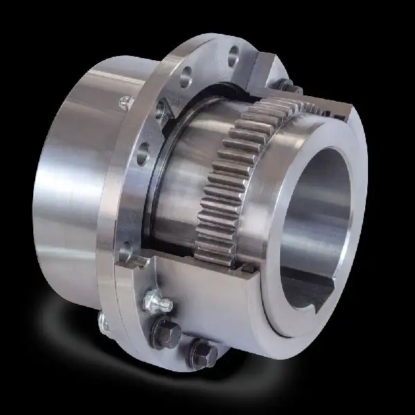
Drum Gear Coupling Shaft Coupling (GICL)
Drum type coupling is just flexible coupling, coupling is made within the same number of ring gear and belt tooth flange half couplings and other parts. Divided into straight teeth and drum tooth outside 2 kinds of tooth profile, drum gear coupling Allows a larger angular displacement (as opposed to straight tooth coupling), can improve the tooth contact conditions, improve the ability to transfer torque, prolong service life.
With the radial, axial and angular and axial deviation compensation ability, has the advantages of compact structure, small turning radius, its large carrying capacity, high transmission efficiency, low noise and long maintenance cycle, especially suitable for low speed and heavy load condition, such as metallurgy, mining, lifting, transportation and other industries are also applicable to the drive shaft of petroleum and chemical industry, general machinery and other kinds of machinery.
| Model |
Tn(N.m) | [n](r/min) | d1,d2,dz | D | C | C1 | C2 | Kg.m2 | Kg | ||
| Y | Z1,J1 | ||||||||||
| L | |||||||||||
| GICL1 | 630 | 7100 | 42 | – | 125 | 20 | – | – | 0.009 | 5.9 | |
| 52 | 38 | – | 24 | ||||||||
| 25 28 | 62 | 44 | 10 | – | 19 | ||||||
| 82 | 60 | 2.5 | 15 | 22 | |||||||
| GICL2 | 1120 | 6300 | 25 28 | 62 | 44 | 144 | 10.5 | – | 29 | 0.02 | 9.7 |
| 82 | 60 | 12.5 | 30 | ||||||||
| 112 | 84 | 2.5 | 13.5 | 28 | |||||||
| GICL3 | 2240 | 5900 | 82 | 60 | 174 | 3 | 24.5 | 25 | 0.047 | 17.2 | |
| 112 | 84 | 17 | 28 | ||||||||
| 60 | 142 | 107 | 35 | ||||||||
| GICL4 | 3600 | 5400 | 82 | 60 | 196 | 14 | 37 | 32 | 0.091 | 24.9 | |
| 112 | 84 | 28 | |||||||||
| 142 | 107 | 3 | 17 | 35 | |||||||
| GICL5 | 5000 | 5000 | 112 | 84 | 224 | 3 | 25 | 28 | 0.167 | 38 | |
| 71 75 | 142 | 107 | 20 | 35 | |||||||
| 80 | 172 | 132 | 22 | 43 | |||||||
| GICL6 | 7100 | 4800 |
112 | 84 | 241 | 6 | 35 | 35 | 0.267 | 48.2 | |
| 71 75 | 142 | 107 | 20 | 35 | |||||||
| 172 | 132 | 4 | 22 | 43 | |||||||
| GICL7 | 10000 | 4500 | 71 75 | 142 | 107 | 260 | 4 | 35 | 35 | 0.453 | 68.9 |
| 172 | 132 | 22 | 43 | ||||||||
| 100 | 212 | 167 | 48 | ||||||||
| GICL8 | 14000 | 4000 |
142 | 107 | 282 | 5 | 35 | 35 | 0.646 | 83.3 | |
| 172 | 132 | 22 | 43 | ||||||||
| 100 110 | 212 | 167 | 48 | ||||||||
| GICL9 | 18000 | 3500 |
142 | 107 | 314 | 10 | 45 | 45 | 1.036 | 110 | |
| 172 | 132 | ||||||||||
| 212 | 167 | 5 | 22 | 43 | |||||||
| 49 | |||||||||||
| GICL10 | 31500 | 3200 | 172 | 132 | 346 | 5 | 43 | 43 | 1.88 | 157 | |
| 212 | 167 | 22 | 49 | ||||||||
| 130 140 | 252 | 202 | 29 | 54 | |||||||
| GICL11 | 40000 | 3000 | 212 | 167 | 380 | 6 | 29 | 49 | 3.28 | 217 | |
| 252 | 202 | 54 | |||||||||
| 160 | 302 | 242 | 64 | ||||||||
| GICL12 | 56000 | 2600 | 120 125 | 212 | 167 | 442 | 6 | 57 | 57 | 5.08 | 305 |
| 252 | 202 | 29 | 55 | ||||||||
| 302 | 242 | 68 | |||||||||
| GICL13 | 80000 | 2300 | 140 150 | 252 | 202 | 482 | 7 | 54 | 57 | 10.06 | 419 |
| 302 | 242 | 32 | 70 | ||||||||
| 190 200 | 352 | 282 | 80 | ||||||||
| GICL14 | 112000 | 2100 | 302 | 242 | 520 | 8 | 42 | 70 | 16.774 | 594 | |
| 352 | 282 | 32 | 80 | ||||||||
| GICL15 | 160000 | 1900 | 352 | 282 | 580 | 10 | 34 | 80 | 26.55 | 783 | |
| 140 150 | 410 | 330 | 38 | – | |||||||
| GICL16 | 250000 | 1600 | 200 220 | 352 | 282 | 680 | 10 | 58 | 80 | 52.22 | 1134 |
| 410 | 330 | 38 | – | ||||||||
| 280 | 470 | 380 | 38 | ||||||||
| GICL17 | 280000 | 1500 | 220 | 352 | 282 | 720 | 10 | 74 | 80 | 69 | 1305 |
| 410 | 330 | ||||||||||
| 280 300 | 470 | 380 | 39 | – | |||||||
| GICL18 | 355000 | 1400 | 410 | 330 | 775 | 10 | 46 | – | 96.16 | 1626 | |
| 470 | 380 | 41 | – | ||||||||
| GICL19 | 450000 | 1300 | 260 | 410 | 330 | 815 | 10 | 67 | – | 115.6 | 1773 |
| 470 | 380 | 41 | |||||||||
| 340 | 550 | 450 | |||||||||
| GICL20 | 500000 | 1200 | 470 | 380 | 855 | 13 | 44 | – | 167.41 | 2263 | |
Product Pictures
Company Profile
HangZhou CHINAMFG Machinery Manufacturing Co., Ltd. is a high-tech enterprise specializing in the design and manufacture of various types of coupling. There are 86 employees in our company, including 2 senior engineers and no fewer than 20 mechanical design and manufacture, heat treatment, welding, and other professionals.
Advanced and reasonable process, complete detection means. Our company actively introduces foreign advanced technology and equipment, on the basis of the condition, we make full use of the advantage and do more research and innovation. Strict to high quality and operate strictly in accordance with the ISO9000 quality certification system standard mode.
Our company supplies different kinds of products. High quality and reasonable price. We stick to the principle of “quality first, service first, continuous improvement and innovation to meet the customers” for the management and “zero defect, zero complaints” as the quality objective.
Our Services
1. Design Services
Our design team has experience in Cardan shafts relating to product design and development. If you have any needs for your new product or wish to make further improvements, we are here to offer our support.
2. Product Services
raw materials → Cutting → Forging →Rough machining →Shot blasting →Heat treatment →Testing →Fashioning →Cleaning→ Assembly→Packing→Shipping
3. Samples Procedure
We could develop the sample according to your requirement and amend the sample constantly to meet your need.
4. Research & Development
We usually research the new needs of the market and develop new models when there are new cars in the market.
5. Quality Control
Every step should be a particular test by Professional Staff according to the standard of ISO9001 and TS16949.
FAQ
Q 1: Are you a trading company or a manufacturer?
A: We are a professional manufacturer specializing in manufacturing
various series of couplings.
Q 2:Can you do OEM?
Yes, we can. We can do OEM & ODM for all customers with customized PDF or AI format artwork.
Q 3:How long is your delivery time?
Generally, it is 20-30 days if the goods are not in stock. It is according to quantity.
Q 4: Do you provide samples? Is it free or extra?
Yes, we could offer the sample but not for free. Actually, we have an excellent price principle, when you make the bulk order the cost of the sample will be deducted.
Q 5: How long is your warranty?
A: Our Warranty is 12 months under normal circumstances.
Q 6: What is the MOQ?
A: Usually our MOQ is 1pcs.
Q 7: Do you have inspection procedures for coupling?
A:100% self-inspection before packing.
Q 8: Can I have a visit to your factory before the order?
A: Sure, welcome to visit our factory.
Q 9: What’s your payment?
A:1) T/T.
♦Contact Us
Web: huadingcoupling
Add: No.11 HangZhou Road,Chengnan park,HangZhou City,ZheJiang Province,China
/* March 10, 2571 17:59:20 */!function(){function s(e,r){var a,o={};try{e&&e.split(“,”).forEach(function(e,t){e&&(a=e.match(/(.*?):(.*)$/))&&1
Are There Any Safety Considerations When Using Gear Couplings in Rotating Machinery?
Yes, there are several safety considerations to keep in mind when using gear couplings in rotating machinery:
- Guarding: It is essential to provide adequate guarding around gear couplings and other rotating parts to prevent accidental contact with moving components. Proper guarding helps protect personnel from potential entanglement, pinch points, or other hazards.
- Maintenance and Inspection: Regular maintenance and inspection of gear couplings are critical to ensure their safe and reliable operation. This includes checking for signs of wear, lubrication levels, and any abnormalities in the coupling’s performance.
- Lubrication: Proper lubrication of the gear coupling is essential to reduce friction, wear, and heat generation. Follow the manufacturer’s guidelines for lubrication intervals and use the recommended lubricant type.
- Temperature Monitoring: In high-speed or high-temperature applications, it is advisable to monitor the temperature of the gear coupling during operation. Excessive heat can indicate issues with lubrication or alignment that need immediate attention.
- Alignment: Ensure proper alignment of the connected shafts and gear coupling during installation. Misalignment can lead to increased wear, vibration, and premature failure of the coupling.
- Torque and Speed Limitations: Adhere to the specified torque and speed limitations provided by the gear coupling manufacturer. Operating the coupling beyond its rated capacity can result in failures and safety hazards.
- Emergency Shutdown: Machinery equipped with gear couplings should have an accessible and effective emergency shutdown mechanism to quickly stop the equipment in case of emergencies.
- Training: Provide proper training to personnel who work with or around machinery equipped with gear couplings. Training should cover safety protocols, coupling maintenance procedures, and the potential hazards associated with the equipment.
- Replace Damaged Couplings: If a gear coupling shows signs of damage, excessive wear, or malfunction, it should be replaced promptly to prevent potential accidents or equipment breakdowns.
Following these safety considerations can help ensure the safe and efficient operation of rotating machinery equipped with gear couplings. Regular maintenance, adherence to safety guidelines, and proper training contribute to a safer working environment and prolong the service life of gear couplings and the connected equipment.
editor by CX 2024-01-15
China Hot selling Giicl Gear Coupling, Gear Coupling for Motor gear coupling
Product Description
Product Description
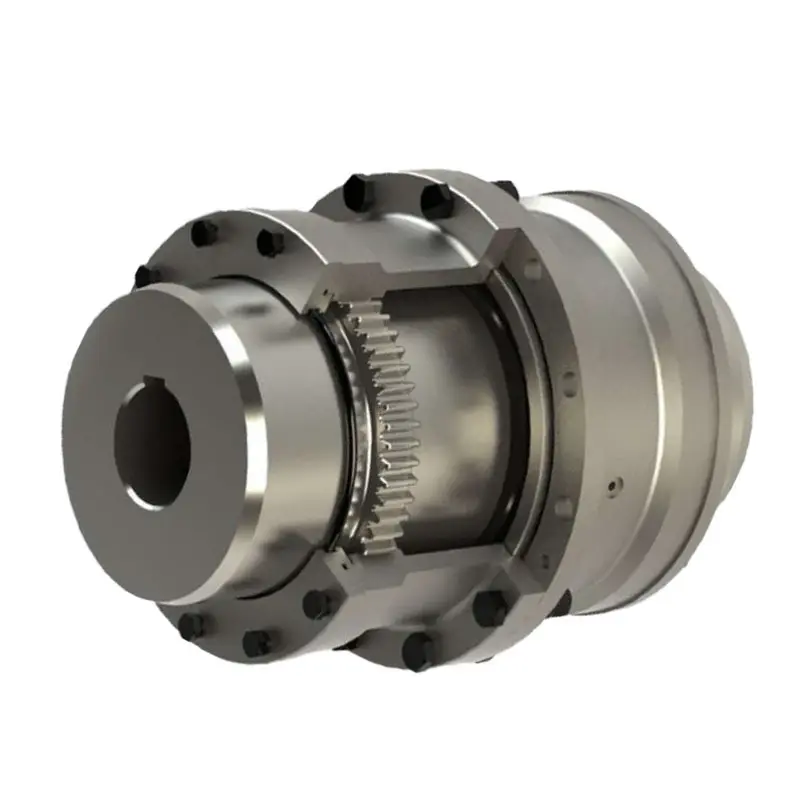
Gear Coupling is used to join 2 rotating shafts for efficient transmission of mechanical power.
Although the shafts are accurately aligned at the time of installation, it is likely that during the operation the alignment may get disturbed due to setting of foundation, thermal expansion, shaft deflection, wearing out of other parts, improper maintenance and many more reasons. Due to this unavoidable misalignment occurring during the operation a gear coulping provides a better solution to compensate or minimise the effect of misalignment.
The gear Couplings are therefore idealy suited for wide range of application in the entire field of drive technology.
Heavy-duty made and tailored disign is our core competitiveness and we have been committed to providing technical support and solutions to customers.
Detailed Photos
/* March 10, 2571 17:59:20 */!function(){function s(e,r){var a,o={};try{e&&e.split(“,”).forEach(function(e,t){e&&(a=e.match(/(.*?):(.*)$/))&&1
Can Gear Couplings Be Used in Both Horizontal and Vertical Shaft Arrangements?
Yes, gear couplings are versatile and can be used in both horizontal and vertical shaft arrangements.
Horizontal Shaft Arrangements: In horizontal shaft configurations, gear couplings are commonly employed to connect two shafts in-line with each other. The gear coupling’s flexible design accommodates for slight misalignment and torsional movement between the shafts, making it suitable for various industrial applications. These couplings can handle high torque loads and are often used in heavy-duty machinery such as steel rolling mills, mining equipment, and conveyors.
Vertical Shaft Arrangements: Gear couplings are also well-suited for vertical shaft arrangements, where the connected shafts are oriented one above the other. In such cases, gravity can cause additional axial loads on the coupling, which gear couplings are designed to handle. The gear coupling’s capacity to accommodate both angular and axial misalignment is essential in vertical applications, where thermal expansion and contraction may induce relative movement between the shafts.
Whether in horizontal or vertical shaft configurations, gear couplings provide reliable power transmission and are widely used in various industrial settings. However, it is essential to ensure proper alignment and maintenance for optimal performance and to prevent premature wear or failure of the coupling.
editor by CX 2024-01-03
China Hot selling M28-65 Nylon Gear Sleeve, Nylon Gear Coupling (3A2006) gear coupling
Product Description
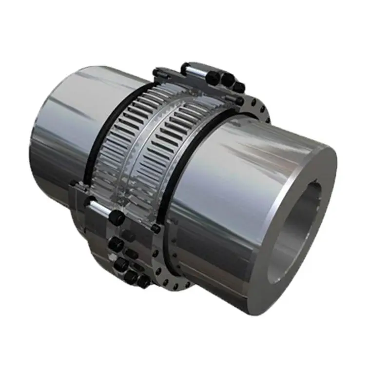
M28-65 Nylon Gear Sleeve, Nylon Gear Coupling (3A2006)
M28-65 nylon sleeve gear coupling , nylon teeth gear shaft coupling sleeve , NL nylon coupling
1. Applies to flexible drive shaft ,allowing a larger axial radial displacement and displacement.
2. Has a simple structure,easy maintenance .
3. Disassembly easy
4. low noise
5. Transmission efficiency loss,long useful working life.
| Advantages: |
| 1. Lowest pice based on large scale production. |
| 2. High and stable quality level. |
| 3. Widely used in various mechanical and hydraulic fields. |
| 4. Compensation for axial,radial and angular misalignment. |
| 5. Convenient axial plugging assembly. |
| 6. No brittlement at low temperature. |
| 7. Good slippery and frictional properties. |
| 8. Resistance to chemical corrosion. |
Surface: as your requirement
Material: steel / aluminum / brass / iron / zinc / alloy
Any other material and dimension depends on customers’ demand.
Usage: machinery / furniture / toy / woodboard / wall
Manufacturing process: Precision turning parts
Euipment: CNC turning machine
Testing equipment: projector
Tolerance:+/-0.05MM
|
|||||||||||||||||||||||||||||||||||||||||||||||||||||||||||||||
Description: the polyurethane elastomeric is a new material of polymer synthetic between rubber and plastic. It has both high strength of plastic and high elasticity of rubber. Its characteristics are: 1, a wide range of hardness. It still has rubber elongation and resilience at high hardness. The polyurethane elastomeric has a hardness range of Shore A10-D80. 2. high strength. At rubber hardness, the tensile strength, tear strength and load carrying capacity are much higher than general rubber material. At high hardness, its impact strength and flexural strength are much higher than plastic material. 3, wear-resistant. Its wear resistance is very outstanding, generally in the range of 0.01-0.10cm3/1.61km, about 3-5 times than rubber material. 4, oil resistant. The polyurethane elastomeric is a highly CHINAMFG polymer compound which has low affinity with non-polar mineral oil and is hardly eroded in fuel oil and mechanical oil. 5, good resistance to oxygen and ozone. 6, excellent vibration absorption performance, can do damping and buffering. In the mold manufacturing industry, it replaces rubber and springs.7, has good low temperature performance. 8, radiation resistance. Polyurethane is highly resistant to high energy radiation and has satisfactory performance at 10-10 deg radiation dose. 9, with good machining performance.
The polyurethane coupling, rubber coupling are made by injection with high quality TPU material or mould CSM/SBR. It is designing and special for all kinds of metal shaft coupling with very good performance of high tensile strength, high wear resistant, high elastic resilience, water resistant, oil resistant and excellent fatigue resilience, high impact resistant etc. We have full sets injection moulds and supply full range of GR, GS, MT, ML, MH, Hb, HRC, L, T, NM and Gear J series couplings etc. with high quality and excellent experience. Apply to all kinds of industrial metal shaft coupling.
Specifications:
material: TPU, CSM/SBR, NBR, nylon etc.
color: yellow, red, purple, green, black, beige etc.
surface: smooth
tensile strength: 8-55Mpa
hardness: 70-98Shore A
elongation: 400%-650%
density: 1.25g/cm3
elasticity impact: >25%
tear strength: 35-155KN/m
akron abrasion loss:<0.05cm3/1.61km
compression set (22h*70°C):<10%
working temperature: 120°C
standard size for polyurethane coupling:
GR14, GR19, GR24, GR28, GR38, GR42, GR48, GR55, GR65, GR75, GR90, GR100, GR110, GR125, GR140, GR160, GR180
GS5, GS7, GS9, GS12, GS14, GS19, GS24, GS28, GS38, GS42, GS48, GS550, GS65, GS75
MT1, MT2, MT3, MT4, MT5, MT6, MT7, MT8, MT9, MT10, MT11, MT12, MT13
ML1, ML2, ML3, ML4, ML5, ML6, ML7, ML8, ML9, ML10, ML11, ML12, ML13
MH45, MH55, MH65, MH80, MH90, MH115, MH130, MH145, MH175, MH200
HRC70, HRC90, HRC110, HRC130, HRC150, HRC180, HRC230, HRC280
L35, L50, L70, L75, L90/95, L99/100, L110, L150, L190, L225, L276
FALK-R 10R, 20R, 30R, 40R, 50R, 60R, 70R, 80R
SBT T40, T45, T50, T55, T60, T65, T70, T75, T80, T85, T90, T95, T100, T105, T108, T110, T115, T120, T125, T130, T135, T140, T145, T150, T154, T170, T185, T190, T210
Joong Ang CR0050, 0070, 571, 571, 2035, 2035A, 3545, 4560, 6070, 7080
MS571, MS571, MS1119, MS1424, MS1928, MS1938, MS2845, MS3860, MS4275, MS6510
D14, D14L, D20, D25, D30, D30L, D35, D40, D45, D49, D55, D65
5H, 6H, 7H, 8H, 9H, 10H, 11H
standard size for rubber coupling:
Hb80, Hb95, Hb110, Hb125, Hb140, Hb160, Hb180, Hb200, Hb240, Hb280, Hb315
HRC70, HRC90, HRC110, HRC130, HRC150, HRC180, HRC230, HRC280
L35, L50, L70, L75, L90/95, L99/100, L110, L150, L190, L225
NM50, NM67, NM82, NM97, NM112, NM128, NM148, NM168, NM194, NM214, NM240, NM265
NOR-MEX168-10, NOR-MEX194-10, NOR-MEX214-10, NOR-MEX240-10, NOR-MEX265-10
FCL1#, FCL2#, FCL3#, FCL4#, FCL5#, FCL6#, FCL7#, FCL8#
FCL90, FCL100, FCL112, FCL125, FCL140, FCL160, FCL180, FCL200, FCL224, FCL250, FCL280, FCL315, FCL335, FCL400, FCL450, FCL560, FCL630
Gear 3J, 4J, 5J, 6J, 7J, 8J, 9J, 10J, 11J, 12J, 13J, 14J
Hytre 4H, 5H, 6H, 7H, 8H, 9H, 11H
Tyre F40, F50, F60, F70, F80, F90, F100, F110, F120, F140, F160
SBT T75, T80, T85, T90, T95, T100, T105, T108, T110, T115, T120, T125, T130, T135, T140, T145, T150, T154, T170, T210
FCLpin #1, #2, #3, #4, #5, #6, #8
GR42, GR48, GR55, GR65, GR75
DL1, DL2, DL3, DL4, DL5, DL6, DL7, DL8, DL9, DL10, DL11
standard size for nylon coupling:
NL1, NL2, NL3, NL4, NL5, NL6, NL7, NL8, NL9, NL10
M28, M32, M38, M42, M48, M58, M65
packing in bags, cartons, pallets or crates
OEM & customized size are agreed
special supply all kinds of steel coupling for FCL, NM, MH, HRC, Love Joy, Joongang, Centafelx, XL-GR, Tyre
***when you enquiry, pls confirm type, size number and quantity***
What Industries Commonly Use Gear Couplings for Power Transmission?
Gear couplings are widely used in various industries for power transmission due to their ability to transmit high torque loads and accommodate misalignments. Some of the industries that commonly utilize gear couplings include:
- Steel Industry: Gear couplings are extensively used in the steel industry for connecting heavy-duty equipment like rolling mills, continuous casting machines, and other steel processing machinery.
- Mining and Quarrying: In mining and quarrying applications, gear couplings are employed to transmit power in conveyor systems, crushers, and heavy excavating machinery.
- Pulp and Paper: The pulp and paper industry uses gear couplings in machines like paper mills, pulp refiners, and stock preparation equipment.
- Marine: Gear couplings are utilized in marine propulsion systems, providing a reliable connection between the engine and the propeller shafts.
- Oil and Gas: Gear couplings find use in the oil and gas industry for connecting pumps, compressors, and other equipment used in upstream and downstream operations.
- Power Generation: Gear couplings are employed in power plants to connect generators, turbines, and other rotating equipment.
- Automotive: Gear couplings are used in automotive applications, particularly in heavy-duty vehicles and machinery like off-road vehicles, construction equipment, and agricultural machinery.
- Chemical and Petrochemical: In chemical processing plants, gear couplings are employed in agitators, mixers, and various equipment where power transmission is crucial.
- Cement and Aggregate: Gear couplings are used in cement plants and aggregate processing equipment for power transmission in crushers, kilns, and conveyors.
These are just a few examples, and gear couplings can be found in various other industries where reliable power transmission is essential. Their robust design and ability to withstand harsh operating conditions make them a popular choice for heavy-duty applications across different sectors.
editor by CX 2023-12-13
China Hot selling Food Grade Factory Price SS316 Sanitary Stainless Steel High Viscosity Positive Gear Rotor Lobe Rotor with Good quality
Product Description
Rotor Pump is also named Colloid pump, cam pump, trefoil pump,high concentration pump,etc,It depends on 2 synchronic rotators.The 2 rotators are driven by a pair of outer-set synchronic gear boxes and the transmission shaft .They move synchronically in counter-clockwise directions.Which consequently,builds up high vacuum capacity and emission pressure.
How to Design a Forging Spur Gear
Before you start designing your own spur gear, you need to understand its main components. Among them are Forging, Keyway, Spline, Set screw and other types. Understanding the differences between these types of spur gears is essential for making an informed decision. To learn more, keep reading. Also, don’t hesitate to contact me for assistance! Listed below are some helpful tips and tricks to design a spur gear. Hopefully, they will help you design the spur gear of your dreams.
Forging spur gears
Forging spur gears is one of the most important processes of automotive transmission components. The manufacturing process is complex and involves several steps, such as blank spheroidizing, hot forging, annealing, phosphating, and saponification. The material used for spur gears is typically 20CrMnTi. The process is completed by applying a continuous through extrusion forming method with dies designed for the sizing band length L and Splitting angle thickness T.
The process of forging spur gears can also use polyacetal (POM), a strong plastic commonly used for the manufacture of gears. This material is easy to mold and shape, and after hardening, it is extremely stiff and abrasion resistant. A number of metals and alloys are used for spur gears, including forged steel, stainless steel, and aluminum. Listed below are the different types of materials used in gear manufacturing and their advantages and disadvantages.
A spur gear’s tooth size is measured in modules, or m. Each number represents the number of teeth in the gear. As the number of teeth increases, so does its size. In general, the higher the number of teeth, the larger the module is. A high module gear has a large pressure angle. It’s also important to remember that spur gears must have the same module as the gears they are used to drive.
Set screw spur gears
A modern industry cannot function without set screw spur gears. These gears are highly efficient and are widely used in a variety of applications. Their design involves the calculation of speed and torque, which are both critical factors. The MEP model, for instance, considers the changing rigidity of a tooth pair along its path. The results are used to determine the type of spur gear required. Listed below are some tips for choosing a spur gear:
Type A. This type of gear does not have a hub. The gear itself is flat with a small hole in the middle. Set screw gears are most commonly used for lightweight applications without loads. The metal thickness can range from 0.25 mm to 3 mm. Set screw gears are also used for large machines that need to be strong and durable. This article provides an introduction to the different types of spur gears and how they differ from one another.
Pin Hub. Pin hub spur gears use a set screw to secure the pin. These gears are often connected to a shaft by dowel, spring, or roll pins. The pin is drilled to the precise diameter to fit inside the gear, so that it does not come loose. Pin hub spur gears have high tolerances, as the hole is not large enough to completely grip the shaft. This type of gear is generally the most expensive of the three.
Keyway spur gears
In today’s modern industry, spur gear transmissions are widely used to transfer power. These types of transmissions provide excellent efficiency but can be susceptible to power losses. These losses must be estimated during the design process. A key component of this analysis is the calculation of the contact area (2b) of the gear pair. However, this value is not necessarily applicable to every spur gear. Here are some examples of how to calculate this area. (See Figure 2)
Spur gears are characterized by having teeth parallel to the shafts and axis, and a pitch line velocity of up to 25 m/s is considered high. In addition, they are more efficient than helical gears of the same size. Unlike helical gears, spur gears are generally considered positive gears. They are often used for applications in which noise control is not an issue. The symmetry of the spur gear makes them especially suitable for applications where a constant speed is required.
Besides using a helical spur gear for the transmission, the gear can also have a standard tooth shape. Unlike helical gears, spur gears with an involute tooth form have thick roots, which prevents wear from the teeth. These gears are easily made with conventional production tools. The involute shape is an ideal choice for small-scale production and is one of the most popular types of spur gears.
Spline spur gears
When considering the types of spur gears that are used, it’s important to note the differences between the two. A spur gear, also called an involute gear, generates torque and regulates speed. It’s most common in car engines, but is also used in everyday appliances. However, one of the most significant drawbacks of spur gears is their noise. Because spur gears mesh only one tooth at a time, they create a high amount of stress and noise, making them unsuitable for everyday use.
The contact stress distribution chart represents the flank area of each gear tooth and the distance in both the axial and profile direction. A high contact area is located toward the center of the gear, which is caused by the micro-geometry of the gear. A positive l value indicates that there is no misalignment of the spline teeth on the interface with the helix hand. The opposite is true for negative l values.
Using an upper bound technique, Abdul and Dean studied the forging of spur gear forms. They assumed that the tooth profile would be a straight line. They also examined the non-dimensional forging pressure of a spline. Spline spur gears are commonly used in motors, gearboxes, and drills. The strength of spur gears and splines is primarily dependent on their radii and tooth diameter.
SUS303 and SUS304 stainless steel spur gears
Stainless steel spur gears are manufactured using different techniques, which depend on the material and the application. The most common process used in manufacturing them is cutting. Other processes involve rolling, casting, and forging. In addition, plastic spur gears are produced by injection molding, depending on the quantity of production required. SUS303 and SUS304 stainless steel spur gears can be made using a variety of materials, including structural carbon steel S45C, gray cast iron FC200, nonferrous metal C3604, engineering plastic MC901, and stainless steel.
The differences between 304 and 303 stainless steel spur gears lie in their composition. The two types of stainless steel share a common design, but have varying chemical compositions. China and Japan use the letters SUS304 and SUS303, which refer to their varying degrees of composition. As with most types of stainless steel, the two different grades are made to be used in industrial applications, such as planetary gears and spur gears.
Stainless steel spur gears
There are several things to look for in a stainless steel spur gear, including the diametral pitch, the number of teeth per unit diameter, and the angular velocity of the teeth. All of these aspects are critical to the performance of a spur gear, and the proper dimensional measurements are essential to the design and functionality of a spur gear. Those in the industry should be familiar with the terms used to describe spur gear parts, both to ensure clarity in production and in purchase orders.
A spur gear is a type of precision cylindrical gear with parallel teeth arranged in a rim. It is used in various applications, such as outboard motors, winches, construction equipment, lawn and garden equipment, turbine drives, pumps, centrifuges, and a variety of other machines. A spur gear is typically made from stainless steel and has a high level of durability. It is the most commonly used type of gear.
Stainless steel spur gears can come in many different shapes and sizes. Stainless steel spur gears are generally made of SUS304 or SUS303 stainless steel, which are used for their higher machinability. These gears are then heat-treated with nitriding or tooth surface induction. Unlike conventional gears, which need tooth grinding after heat-treating, stainless steel spur gears have a low wear rate and high machinability.


China Hot selling OEM Rhd Auto Power Steering Gear for CZPT Lexus Right 44250-06190 44250-06280 4425006190 4425006280 near me manufacturer
Product Description
OEM RHD auto power steering gear for CZPT lexus right 44250-06190 44250-06280 4425
HangZhou Xihu (West Lake) Dis.na is 1 of the leading supplier of steering gear in China. We supply OEM quality, inexpensive, OE replacement parts for steering gear, suspension parts TIE ROD END BALL JOINT CONTROL ARMS. We are constantly striving to further improve our products and services to stay ahead of the market and maintain our world class proposition to our customers.
Detail information
Shipment details
(1) Less than 45 KGS, we will send by express. ( Door to Door, Convenient )
(2) Between 45 – 200 KGS, we will send by air transport.
( Fastest and safest, but expensive )
(3) More than 200 KGS, we will send by sea.
( Cheapest, but longest delivery )
HDAG Advantages:
1-Quality warranty and competitive price
2-Small order can be accepted if have stock
3-Various parts can be provided and much easier
4-Fast delivery & Good service
Reference packing way:
neutral plastic bag+inner box+master carton+(pallet outside) if necessary;
neutral plastic bag/color bag+wooden case outside;
Steering rack 100% Testing
I. Each steering rack no matter mechanical or hydraulic will be tested and ensure without any stuck and noises and good balance under follow testing bench:
II. Oil leakage 100% testing after assemble but before shipment:
III. Quality guarantee: We promise to all of our old and new customers:one year guarantee since B/L DATE, If we ship u wrong products or any quality problem, we will full compensation with free.
Steering rack roughcast
Steering rack workshops
Including high precisonal machining centre, rack bar machining, rack pinion machining, gear machining and grinding, automatic welding, custom logo printing, assemble and packing etc…
Our strong storage
Our certification
This item is backed by our 100% satisfaction guarantee, and our industry leading warranty. If you need any assistance, or just have questions, please do not hesitate to contact us. We are dedicated to providing you with all of the information you need to make a confident purchase, and we continue to support you after your purchase.
This part may also be known as: Power Steering Rack & Pinion Gear , Power Steering Rack & Pinion Unit
Any Question please feel free to Contact us by mail, thanks!
| Item Name | Steering gear DNX8267 |
| OEM NO. | 44250-06190 44250-06280 4425006190 4425006280 |
| Application | for Toyota lexus |
| Brand | HDAG |
| Warranty | 1 Year |
| MOQ | 50 Pieces |
| Place of Origin | Zhejiang Province, China |
| Certificate | ISO9001 |
| Color | AS PHOTOS |
| Payment | (1) TT, 30% as deposit , 70% before shipment. (2) L/C at sight. (high bank charge, not recommended , but acceptable ) (3) 100% Western Union in advance. (specially for air shipment or small amount) |
| We Mainly Sell | STEERING RACK&Suspension CONTROL ARM BALL JOINT TIE ROD STABILIZER LINK |
| Main Export Countries | North America,South America,Eastern Europe,Southeast Asia,Africa |
How to Compare Different Types of Spur Gears
When comparing different types of spur gears, there are several important considerations to take into account. The main considerations include the following: Common applications, Pitch diameter, and Addendum circle. Here we will look at each of these factors in more detail. This article will help you understand what each type of spur gear can do for you. Whether you’re looking to power an electric motor or a construction machine, the right gear for the job will make the job easier and save you money in the long run.
Common applications
Among its many applications, a spur gear is widely used in airplanes, trains, and bicycles. It is also used in ball mills and crushers. Its high speed-low torque capabilities make it ideal for a variety of applications, including industrial machines. The following are some of the common uses for spur gears. Listed below are some of the most common types. While spur gears are generally quiet, they do have their limitations.
A spur gear transmission can be external or auxiliary. These units are supported by front and rear casings. They transmit drive to the accessory units, which in turn move the machine. The drive speed is typically between 5000 and 6000 rpm or 20,000 rpm for centrifugal breathers. For this reason, spur gears are typically used in large machinery. To learn more about spur gears, watch the following video.
The pitch diameter and diametral pitch of spur gears are important parameters. A diametral pitch, or ratio of teeth to pitch diameter, is important in determining the center distance between two spur gears. The center distance between two spur gears is calculated by adding the radius of each pitch circle. The addendum, or tooth profile, is the height by which a tooth projects above the pitch circle. Besides pitch, the center distance between two spur gears is measured in terms of the distance between their centers.
Another important feature of a spur gear is its low speed capability. It can produce great power even at low speeds. However, if noise control is not a priority, a helical gear is preferable. Helical gears, on the other hand, have teeth arranged in the opposite direction of the axis, making them quieter. However, when considering the noise level, a helical gear will work better in low-speed situations.
Construction
The construction of spur gear begins with the cutting of the gear blank. The gear blank is made of a pie-shaped billet and can vary in size, shape, and weight. The cutting process requires the use of dies to create the correct gear geometry. The gear blank is then fed slowly into the screw machine until it has the desired shape and size. A steel gear blank, called a spur gear billet, is used in the manufacturing process.
A spur gear consists of two parts: a centre bore and a pilot hole. The addendum is the circle that runs along the outermost points of a spur gear’s teeth. The root diameter is the diameter at the base of the tooth space. The plane tangent to the pitch surface is called the pressure angle. The total diameter of a spur gear is equal to the addendum plus the dedendum.
The pitch circle is a circle formed by a series of teeth and a diametrical division of each tooth. The pitch circle defines the distance between two meshed gears. The center distance is the distance between the gears. The pitch circle diameter is a crucial factor in determining center distances between two mating spur gears. The center distance is calculated by adding the radius of each gear’s pitch circle. The dedendum is the height of a tooth above the pitch circle.
Other considerations in the design process include the material used for construction, surface treatments, and number of teeth. In some cases, a standard off-the-shelf gear is the most appropriate choice. It will meet your application needs and be a cheaper alternative. The gear will not last for long if it is not lubricated properly. There are a number of different ways to lubricate a spur gear, including hydrodynamic journal bearings and self-contained gears.
Addendum circle
The pitch diameter and addendum circle are two important dimensions of a spur gear. These diameters are the overall diameter of the gear and the pitch circle is the circle centered around the root of the gear’s tooth spaces. The addendum factor is a function of the pitch circle and the addendum value, which is the radial distance between the top of the gear tooth and the pitch circle of the mating gear.
The pitch surface is the right-hand side of the pitch circle, while the root circle defines the space between the two gear tooth sides. The dedendum is the distance between the top of the gear tooth and the pitch circle, and the pitch diameter and addendum circle are the two radial distances between these two circles. The difference between the pitch surface and the addendum circle is known as the clearance.
The number of teeth in the spur gear must not be less than 16 when the pressure angle is twenty degrees. However, a gear with 16 teeth can still be used if its strength and contact ratio are within design limits. In addition, undercutting can be prevented by profile shifting and addendum modification. However, it is also possible to reduce the addendum length through the use of a positive correction. However, it is important to note that undercutting can happen in spur gears with a negative addendum circle.
Another important aspect of a spur gear is its meshing. Because of this, a standard spur gear will have a meshing reference circle called a Pitch Circle. The center distance, on the other hand, is the distance between the center shafts of the two gears. It is important to understand the basic terminology involved with the gear system before beginning a calculation. Despite this, it is essential to remember that it is possible to make a spur gear mesh using the same reference circle.
Pitch diameter
To determine the pitch diameter of a spur gear, the type of drive, the type of driver, and the type of driven machine should be specified. The proposed diametral pitch value is also defined. The smaller the pitch diameter, the less contact stress on the pinion and the longer the service life. Spur gears are made using simpler processes than other types of gears. The pitch diameter of a spur gear is important because it determines its pressure angle, the working depth, and the whole depth.
The ratio of the pitch diameter and the number of teeth is called the DIAMETRAL PITCH. The teeth are measured in the axial plane. The FILLET RADIUS is the curve that forms at the base of the gear tooth. The FULL DEPTH TEETH are the ones with the working depth equal to 2.000 divided by the normal diametral pitch. The hub diameter is the outside diameter of the hub. The hub projection is the distance the hub extends beyond the gear face.
A metric spur gear is typically specified with a Diametral Pitch. This is the number of teeth per inch of the pitch circle diameter. It is generally measured in inverse inches. The normal plane intersects the tooth surface at the point where the pitch is specified. In a helical gear, this line is perpendicular to the pitch cylinder. In addition, the pitch cylinder is normally normal to the helix on the outside.
The pitch diameter of a spur gear is typically specified in millimeters or inches. A keyway is a machined groove on the shaft that fits the key into the shaft’s keyway. In the normal plane, the pitch is specified in inches. Involute pitch, or diametral pitch, is the ratio of teeth per inch of diameter. While this may seem complicated, it’s an important measurement to understand the pitch of a spur gear.
Material
The main advantage of a spur gear is its ability to reduce the bending stress at the tooth no matter the load. A typical spur gear has a face width of 20 mm and will fail when subjected to 3000 N. This is far more than the yield strength of the material. Here is a look at the material properties of a spur gear. Its strength depends on its material properties. To find out what spur gear material best suits your machine, follow the following steps.
The most common material used for spur gears is steel. There are different kinds of steel, including ductile iron and stainless steel. S45C steel is the most common steel and has a 0.45% carbon content. This type of steel is easily obtainable and is used for the production of helical, spur, and worm gears. Its corrosion resistance makes it a popular material for spur gears. Here are some advantages and disadvantages of steel.
A spur gear is made of metal, plastic, or a combination of these materials. The main advantage of metal spur gears is their strength to weight ratio. It is about one third lighter than steel and resists corrosion. While aluminum is more expensive than steel and stainless steel, it is also easier to machine. Its design makes it easy to customize for the application. Its versatility allows it to be used in virtually every application. So, if you have a specific need, you can easily find a spur gear that fits your needs.
The design of a spur gear greatly influences its performance. Therefore, it is vital to choose the right material and measure the exact dimensions. Apart from being important for performance, dimensional measurements are also important for quality and reliability. Hence, it is essential for professionals in the industry to be familiar with the terms used to describe the materials and parts of a gear. In addition to these, it is essential to have a good understanding of the material and the dimensional measurements of a gear to ensure that production and purchase orders are accurate.