
Beskrivelse
The GICL drum shape gear coupling series represents decades of engineering refinement, purpose-built to transmit high torques while accommodating angular, radial, and axial misalignment between connected shafts. Unlike rigid couplings, the crowned-tooth drum profile distributes load uniformly across the full tooth face, dramatically reducing edge stress concentrations even when shafts are slightly out of alignment. This makes the GICL coupling series a trusted solution in British manufacturing plants, offshore platforms, and utilities infrastructure where continuous, uninterrupted power transmission is non-negotiable. The series spans 30 standard sizes — from compact GICL1 units handling 0.8 kN·m at up to 7,100 R/min, right through to the heavy GICL30 rated for 3,200 kN·m at 700 R/min — covering virtually every industrial drive scenario encountered across the United Kingdom’s engineering sector. Built from high-grade alloy steel with precision-ground drum teeth, each coupling is manufactured under strict quality control protocols that mirror the standards expected by UK industrial procurement teams.

Working Principle & Engineering Design
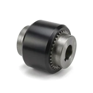
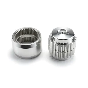
The drum shape gear coupling achieves its superior misalignment tolerance through a fundamentally different tooth geometry compared to conventional straight-tooth gear couplings. The outer sleeve features internal straight teeth, while the inner hubs carry the signature convex, barrel-shaped (drum) external teeth. When the coupling is assembled and the hubs are misaligned relative to one another, the rounded drum tooth profile rocks smoothly within the sleeve tooth space rather than binding at the tooth edges. This rolling contact spreads the transmitted load across a far greater tooth surface area, reducing peak contact stress by a significant margin and extending service life dramatically — particularly under the cyclic loading conditions common in UK steel processing lines and paper mills. The angular compensation capacity reaches 1°30′ per coupling half, and radial displacement values (ΔY) are documented for all 30 sizes in the specification tables below, with GICL30 permitting up to 21.7 mm of radial offset. The design also accommodates axial float, which is critical in applications where thermal expansion of shafting is expected, such as in power generation turbine drives. Lubrication is typically grease-packed at installation, with the sealed sleeve retaining lubricant for extended maintenance intervals — a feature valued by UK plant maintenance teams operating under tight shutdown schedules.
Key Product Advantages
Engineering teams across the United Kingdom consistently choose the GICL drum shape gear coupling over straight-tooth alternatives for a combination of technical and commercial reasons that translate directly into lower total cost of ownership. The crowned tooth geometry is the primary differentiator — it removes the need for perfect shaft alignment during installation, which on large industrial drives can otherwise represent days of precision alignment work. The coupling self-compensates for minor positional drift that occurs as foundations settle or equipment wears, meaning planned maintenance intervals are determined by production schedules rather than coupling degradation. The sealed grease-lubricated design eliminates the continuous oil circulation systems required by some competing coupling types, dramatically simplifying the drive train architecture and reducing auxiliary equipment costs. The broad size range from GICL1 through GICL30 means that a single supplier relationship covers everything from auxiliary pump drives to main mill table gearboxes, simplifying procurement and spares inventory management for UK engineering stores.
Technical Specification Drawings
Dimensional reference drawings for the GICL drum shape gear coupling series, showing principal dimensions D, D1, D2, B, A, C, C1, C2 and shaft hole configurations.


Technical Specifications — GICL1 to GICL4
Torque in kN·m | Speed in R/min | Dimensions in mm | Inertia in kg·m² | Weight in kg
| Type | Limited Torque kN·m | Limited Speed R/min | Shaft Hole d1,d2,d3 (mm) | L–Y | L–J1,Z1 | D | D1 | D2 | B | A | C | C1 | C2 | e | Inertia kg·m² | Weight kg |
|---|---|---|---|---|---|---|---|---|---|---|---|---|---|---|---|---|
| GICL1 | 0.8 | 7100 | 16,18,19 | 42 | – | 125 | 95 | 60 | 115 | 75 | 20/10 | – | 24 | 30 | 0.009 | 5.9 |
| 20,22,24 | 52 | 38 | 2.5 | – | 19 | |||||||||||
| 25,28; 30,32,35,38 | 62/82 | 44/60 | – | 15 | 22 | |||||||||||
| GICL2 | 1.4 | 6300 | 25,28; 30,32,35,38 | 62/82 | 44/60 | 145 | 120 | 75 | 135 | 88 | 10.5/2.5/13.5 | –/12.5 | 29/30/28 | 30 | 0.02 | 9.7 |
| 40,42,45,48 | 112 | 84 | – | – | – | |||||||||||
| GICL3 | 2.8 | 5900 | 30,32,35,38 | 82 | 60 | 170 | 140 | 95 | 155 | 106 | 3 | 24.5/17 | 25/28 | 30 | 0.047 | 17.2 |
| 40,42,45,48; 50,55,56; 60 | 112/142 | 84/107 | – | 35 | ||||||||||||
| GICL4 | 5.0 | 5400 | 32,35,38 | 82 | 60 | 195 | 165 | 115 | 178 | 125 | 3 | 14/17 | 37/28 | 30 | 0.091 | 24.9 |
| 40,42,45,48; 50,55,56; 60,63,65,70 | 112/142 | 84/107 | – | 35 |
GICL5 to GICL19 — Medium Series Specifications
| Type | Torque kN·m | Speed R/min | Shaft Hole d (mm) | L–Y | L–J1 | D | D1 | D2 | B | A | C | e | Inertia kg·m² | Weight kg |
|---|---|---|---|---|---|---|---|---|---|---|---|---|---|---|
| GICL5 | 8.0 | 5000 | 40–56; 60–75; 80 | 112/142/172 | 84/107/132 | 225 | 183 | 130 | 198 | 142 | 3 | 30 | 0.167 | 38 |
| GICL6 | 11.2 | 4800 | 48–56; 60–75; 80,85,90 | 112/142/172 | 84/107/132 | 240 | 200 | 145 | 218 | 160 | 4 | 30 | 0.267 | 48.2 |
| GICL7 | 15.0 | 4500 | 60–75; 80–95; 100 | 142/172/212 | 107/132/167 | 260 | 230 | 160 | 244 | 180 | 4 | 30 | 0.453 | 68.9 |
| GICL8 | 21.2 | 4000 | 65–75; 80–95; 100,110 | 142/172/212 | 107/132/167 | 280 | 245 | 175 | 264 | 193 | 5 | 30 | 0.646 | 83.3 |
| GICL9 | 26.5 | 3500 | 70–75; 80–95; 100–125 | 142/172/212 | 107/132/167 | 315 | 270 | 200 | 284 | 208 | 5 | 30 | 1.036 | 110 |
| GICL10 | 42.5 | 3200 | 80–95; 100–125; 130,140 | 172/212/252 | 132/167/202 | 345 | 300 | 220 | 330 | 249 | 5 | 30 | 1.88 | 157 |
| GICL11 | 60.0 | 3000 | 100,110,120; 130–150; 160 | 212/252/302 | 167/202/242 | 380 | 330 | 260 | 360 | 267 | 6 | 40 | 3.28 | 217 |
| GICL12 | 80.0 | 2600 | 120; 130–150; 160,170,180 | 212/252/302 | 167/202/242 | 440 | 380 | 290 | 416 | 313 | 6 | 40 | 5.08 | 305 |
| GICL13 | 112 | 2300 | 140,150; 160,170,180; 190,200 | 252/302/352 | 202/242/282 | 480 | 420 | 320 | 476 | 364 | 7 | 40 | 10.06 | 416 |
| GICL14 | 160 | 2100 | 160,170,180; 190,200,220 | 302/352 | 242/282 | 520 | 465 | 360 | 532 | 415 | 8 | 40 | 16.774 | 594 |
| GICL15 | 224 | 1900 | 190,200,220; 240,250 | 352/410 | 282/330 | 580 | 510 | 400 | 556 | 429 | 10 | 40 | 26.55 | 783 |
| GICL16 | 355 | 1600 | 200,220; 240,250,260; 280 | 352/410/470 | 282/330/380 | 680 | 595 | 465 | 640 | 501 | 10 | 50 | 52.22 | 1134 |
| GICL17 | 400 | 1500 | 220; 240,250,260; 280,300 | 352/410/470 | 282/330/380 | 720 | 645 | 495 | 672 | 512 | 10 | 50 | 69 | 1305 |
| GICL18 | 500 | 1400 | 240,250,260; 280,300,320 | 410/470 | 330/380 | 775 | 675 | 520 | 702 | 524 | 10 | 50 | 96.16 | 1626 |
| GICL19 | 630 | 1300 | 260; 280,300,320; 340 | 410/470/550 | 330/380/450 | 815 | 715 | 560 | 744 | 560 | 10 | 50 | 115.6 | 1773 |
GICL20 to GICL30 — Heavy Duty Series Specifications
| Type | Torque kN·m | Speed R/min | Shaft Hole d (mm) | L–Y | L–J1 | D | D1 | D2 | B | A | C | e | Inertia kg·m² | Weight kg |
|---|---|---|---|---|---|---|---|---|---|---|---|---|---|---|
| GICL20 | 710 | 1200 | 280,300,320; 340,360 | 470/550 | 380/450 | 855 | 755 | 585 | 786 | 595 | 13 | 50 | 167.41 | 2263 |
| GICL21 | 900 | 1100 | 300,320; 340,360,380 | 470/550 | 380/450 | 915 | 795 | 620 | 808 | 611 | 13 | 50 | 215.7 | 2593 |
| GICL22 | 950 | 950 | 340,360,380; 400 | 550/650 | 450/540 | 960 | 840 | 665 | 830 | 632 | 13 | 60 | 278.07 | 3036 |
| GICL23 | 1120 | 900 | 360,380; 400,420 | 550/650 | 450/540 | 1010 | 890 | 710 | 870 | 666 | 13 | 60 | 397.4 | 3668 |
| GICL24 | 1250 | 875 | 380; 400,420,450 | 550/650 | 450/540 | 1050 | 925 | 730 | 890 | 685 | 15 | 60 | 448.1 | 3946 |
| GICL25 | 1400 | 850 | 400,420,450,480 | 650 | 540 | 1120 | 970 | 770 | 930 | 724 | 15 | 60 | 564.64 | 4443 |
| GICL26 | 1600 | 825 | 420,450,480,500 | 650 | 540 | 1160 | 990 | 800 | 950 | 733 | 15 | 60 | 637.4 | 4791 |
| GICL27 | 1800 | 800 | 450,480,500; 530 | 650/800 | 540/680 | 1210 | 1060 | 850 | 958 | 739 | 15 | 70 | 866.26 | 5758 |
| GICL28 | 2000 | 770 | 480,500; 530,560 | 650/800 | 540/680 | 1250 | 1080 | 890 | 1034 | 805 | 20 | 70 | 1020.76 | 6232 |
| GICL29 | 2800 | 725 | 500; 530,560,600 | 650/800 | 540/680 | 1340 | 1200 | 960 | 1034 | 792 | 20 | 80 | 1450.84 | 7549 |
| GICL30 | 3200 | 700 | 560,600,630 | 800 | 680 | 1390 | 1240 | 1005 | 1050 | 806 | 20 | 80 | 1947.17 | 9514 |
Allowable Radial Compensation ΔY (mm) — All Sizes
Note: (1) Quality and rotational inertia are approximations based on minimum shaft diameter and maximum shaft length. (2) For D2 ≥ 465 mm, seal ring uses circular-surface rubber felting. (3) J1 axle hole may not use shaft-end retaining ring if not required. (4) Allowable angular compensation: 1°30′. (5) Allowable radial compensation ΔY values listed below.
| Type | GICL1 | GICL2 | GICL3 | GICL4 | GICL5 | GICL6 | GICL7 | GICL8 | GICL9 | GICL10 |
|---|---|---|---|---|---|---|---|---|---|---|
| ΔY (mm) | 1.96 | 2.36 | 2.75 | 3.27 | 3.8 | 4.3 | 4.7 | 5.24 | 5.63 | 6.81 |
| Type | GICL11 | GICL12 | GICL13 | GICL14 | GICL15 | GICL16 | GICL17 | GICL18 | GICL19 | GICL20 |
| ΔY (mm) | 7.46 | 8.77 | 10.08 | 11.15 | 11.36 | 13.3 | 13.87 | 14.53 | 15.71 | 16.49 |
| Type | GICL21 | GICL22 | GICL23 | GICL24 | GICL25 | GICL26 | GICL27 | GICL28 | GICL29 | GICL30 |
| ΔY (mm) | 17.02 | 17.28 | 18.06 | 18.6 | 19.4 | 19.92 | 19.92 | 21.1 | 21.1 | 21.7 |
Application Scenarios Across UK Industry
The GICL drum shape gear coupling has found a permanent place in the equipment inventories of UK industrial operations because it addresses a combination of challenges that no single alternative coupling type resolves as comprehensively. In the steel and metals sector — concentrated in areas including South Wales, Sheffield, and Teesside — rolling mill main drives and roughing stand gearboxes impose peak torque reversals on couplings that would quickly destroy elastomeric types. The GICL’s all-steel construction absorbs these shock loads without fatigue. Power generation facilities, both conventional and renewable, use GICL couplings to connect turbine output shafts to generator input flanges, relying on the angular compensation to protect costly generator bearings from misalignment-induced radial loads. The chemical and petrochemical processing industry, operating refineries and chemical plants across the north of England and Scotland, values the sealed lubrication system since volatile or corrosive atmospheres make exposed oil-bath couplings unsuitable. Marine engineering yards and offshore platform operators in Aberdeen use GICL couplings on propulsion shaft lines and thruster drives, where weight, compactness, and reliability under continuous vibration are all critical. The pulp and paper sector, with mills in Scotland and Northern Ireland, deploys the medium-range GICL11 through GICL16 units on paper machine drives where smooth torque transmission protects delicate web formation.
Ever Power Manufacturing & Custom Engineering
Ever Power operates a dedicated manufacturing facility equipped with CNC gear hobbing machines, precision cylindrical grinders, and coordinate measuring equipment, enabling production of drum shape gear couplings to tolerances that meet or exceed those specified in GB/T 5272 and ISO equivalent standards. The workshop processes alloy steel billets through forging, normalising, rough machining, gear cutting, induction hardening, and precision finish grinding entirely in-house — a vertically integrated capability that gives the engineering team complete control over quality at every stage, from raw material to finished assembled coupling.
The customisation service is one of Ever Power’s most valued capabilities among UK procurement teams. Beyond the 30 standard GICL sizes, the engineering team regularly produces bespoke variants with non-standard bore diameters, special keyway configurations, modified flange patterns to match legacy equipment bolt circles, and extended or reduced overall lengths to suit tight drive bay envelopes. Coupling halves in stainless steel or special high-strength grades are available for corrosive or high-temperature environments. Split-sleeve configurations, suitable for applications where disassembly without shaft withdrawal is required, can be engineered to order. UK customers are encouraged to submit drawings, 3D models, or even worn originals for reverse engineering — the team will confirm feasibility and provide a quotation typically within 72 hours of receiving complete information.

Customer Success: Real Applications, Proven Results
Industrial operators across the UK and Europe share their experience with Ever Power GICL drum shape gear couplings.
“We were replacing a competitor’s straight-tooth coupling on our bar mill roughing stands every 14 to 18 months — the edge loading was catastrophic under full reversal loads. After switching to the GICL24 drum type from Ever Power, we’re past 38 months on the first set and the teeth still look like new at the last inspection. The radial compensation is a genuine benefit because our mill table foundations do shift seasonally. The customised bore sizing for our non-standard 415 mm shaft was delivered on time and machined to an excellent standard. Technical support during selection was professional and practical — they recommended the correct size based on our actual peak torque data, not just the nameplate figures.”
“Operating diesel generator sets on a North Sea platform, we need couplings that tolerate the vibration and thermal cycles without opening up gear mesh clearances over time. The GICL18 units we sourced from Ever Power have performed well beyond our maintenance interval targets. The sealed grease design is ideal for our environment — we cannot have oil leak hazards near generator sets. Ever Power supplied units with stainless steel hardware and a modified flange pattern to match our generator coupling adapter, with dimensional drawings confirmed before manufacture. Quality of machining and surface finish on the drum teeth was noticeably superior to previous suppliers. Price-competitive against UK-sourced alternatives, with shorter lead times.”
“We run multiple paper machine sections on one continuous line, and any coupling-induced torque ripple shows up immediately as caliper variation in the finished sheet. The GICL13 units run smoother than any coupling we’ve used before — we attribute this to the precision grinding of the drum tooth profiles. Four units have been running continuously for two years without any maintenance beyond a scheduled grease check at 12 months. The original quotation from Ever Power was detailed and included a selection justification document that our maintenance manager could present to engineering management — that level of support at the enquiry stage is rare from overseas suppliers and was one of the reasons we placed the order.”
Frequently Asked Questions
Send your shaft sizes, torque data and any custom requirements — our engineers will respond with a precise recommendation and competitive price.
📧 Get a Quote: [email protected]